Creating 3D model of airplane with Google ScetchUp - part one Some times ago I modeled many aircrafts in Google ScetchUp. When people seen my models, they have a questions. For answer I write this "lesson".
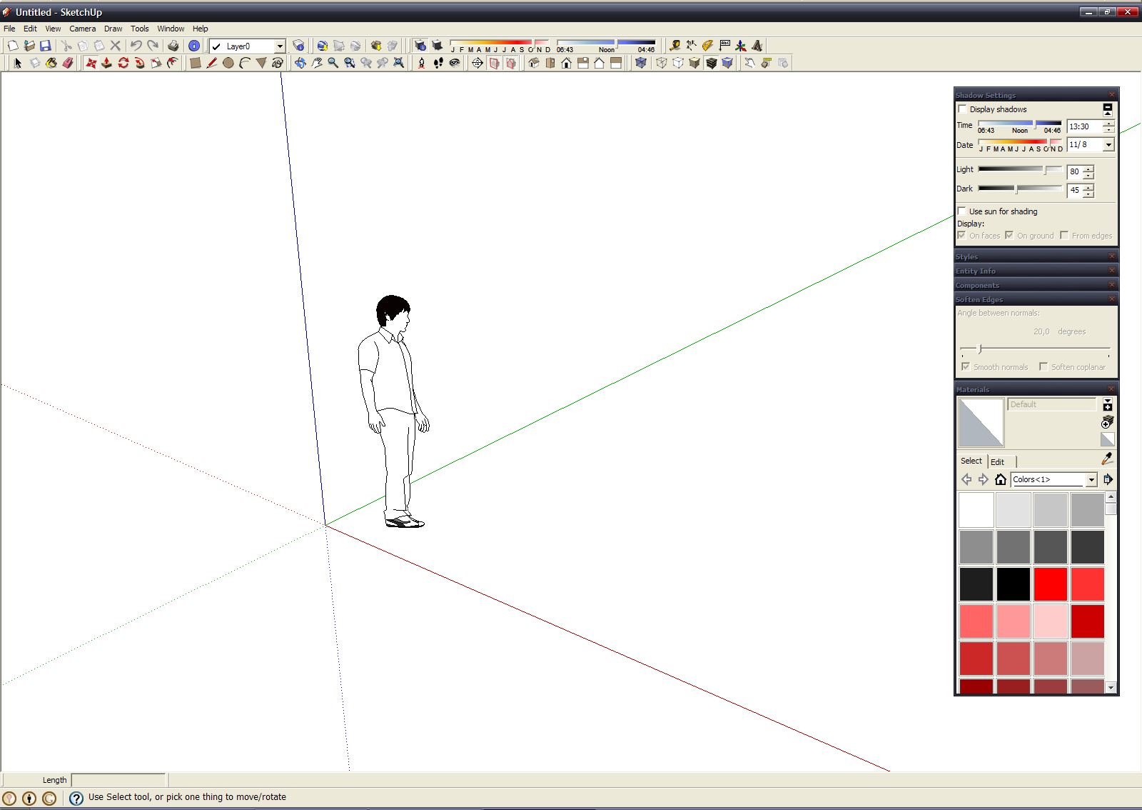
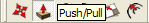
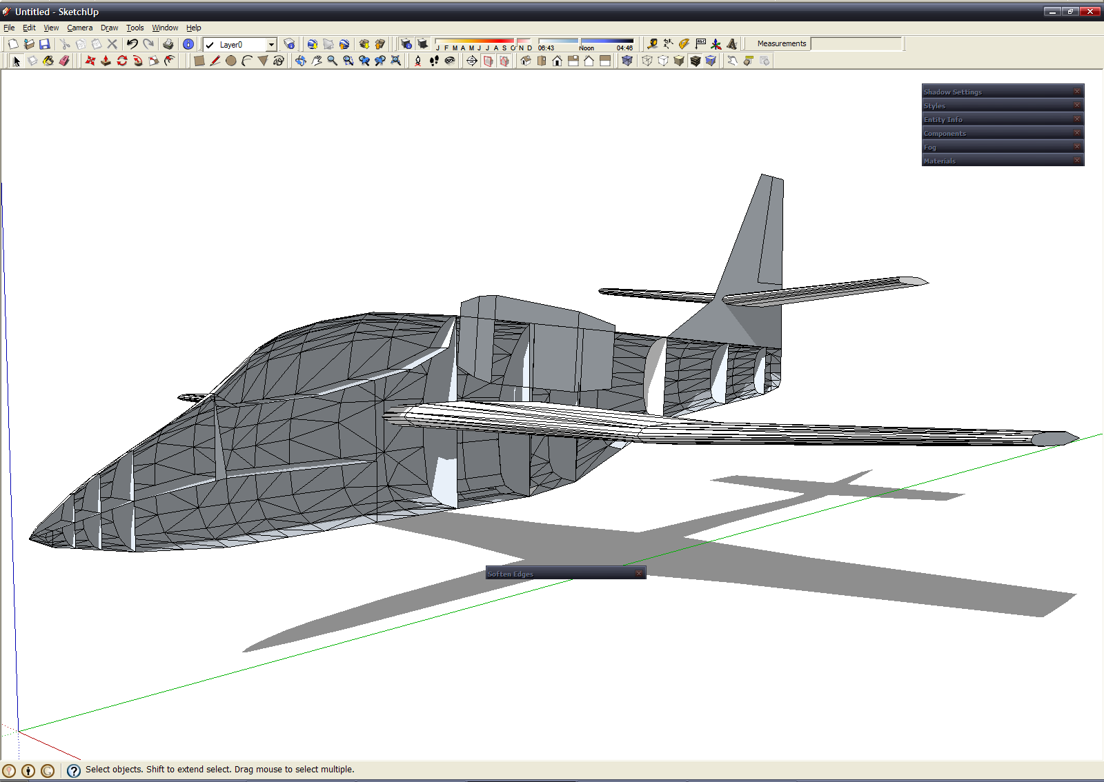
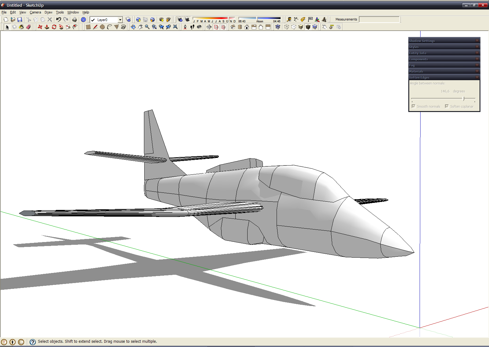
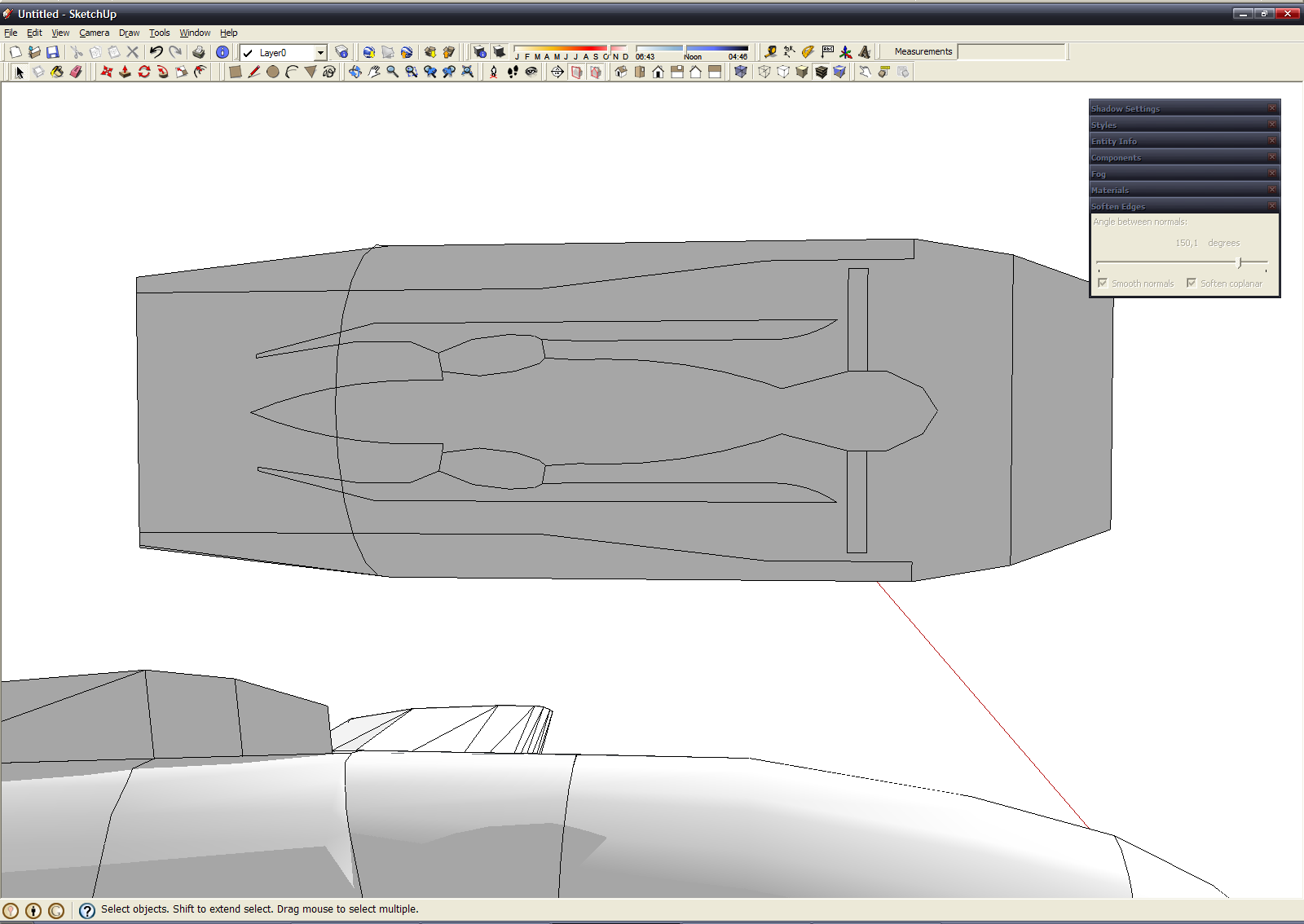
At first, I wrote on my native, russian language, year ago - at july of 2010. Now I try translate it into english (also sorry for my bad english... I write at english and use Google Translator for check it, but some errors are possible) I used Google ScetchUp 7.0 (although I used all version from 5.0 to 8.0... changes are minimal... some command was add, some renamed, but generaly interface is same) with english interface (in some spheres, such as CG or 3D I use english software, becouse russian translation sometimes not are good) ScetchUp window looks like this: 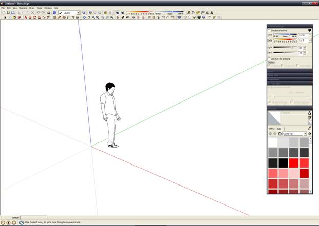
All toolbars are open. I dont use all buttons (but default are not enough), but I don't want open main menu at nonessential things. For open some toolbars you must execute View->Toolbars->%toolbars_name% in main menu. Although at left view some little windows - Shadow settings, Styles, Soften Edges, Materials (others almost never used, even though they are open). This things open in menu Window (also you can hide or show some windows in "Hide/Show" dialog), also you can minimise any window at thin bar when you doubleclick at window caption
The units I use the metric - meters. This feature you can change into "Window->Preferens->Templete->Engineering-meters" or into "Window->Model info->Units". I dont use imperial units, because it not common in my country - I need some time when I hear "inch, foot, mile", for imagine these distance and convert into habitual centimeter, meter and kilometers =) Okay, we are prepared for start modeling process.
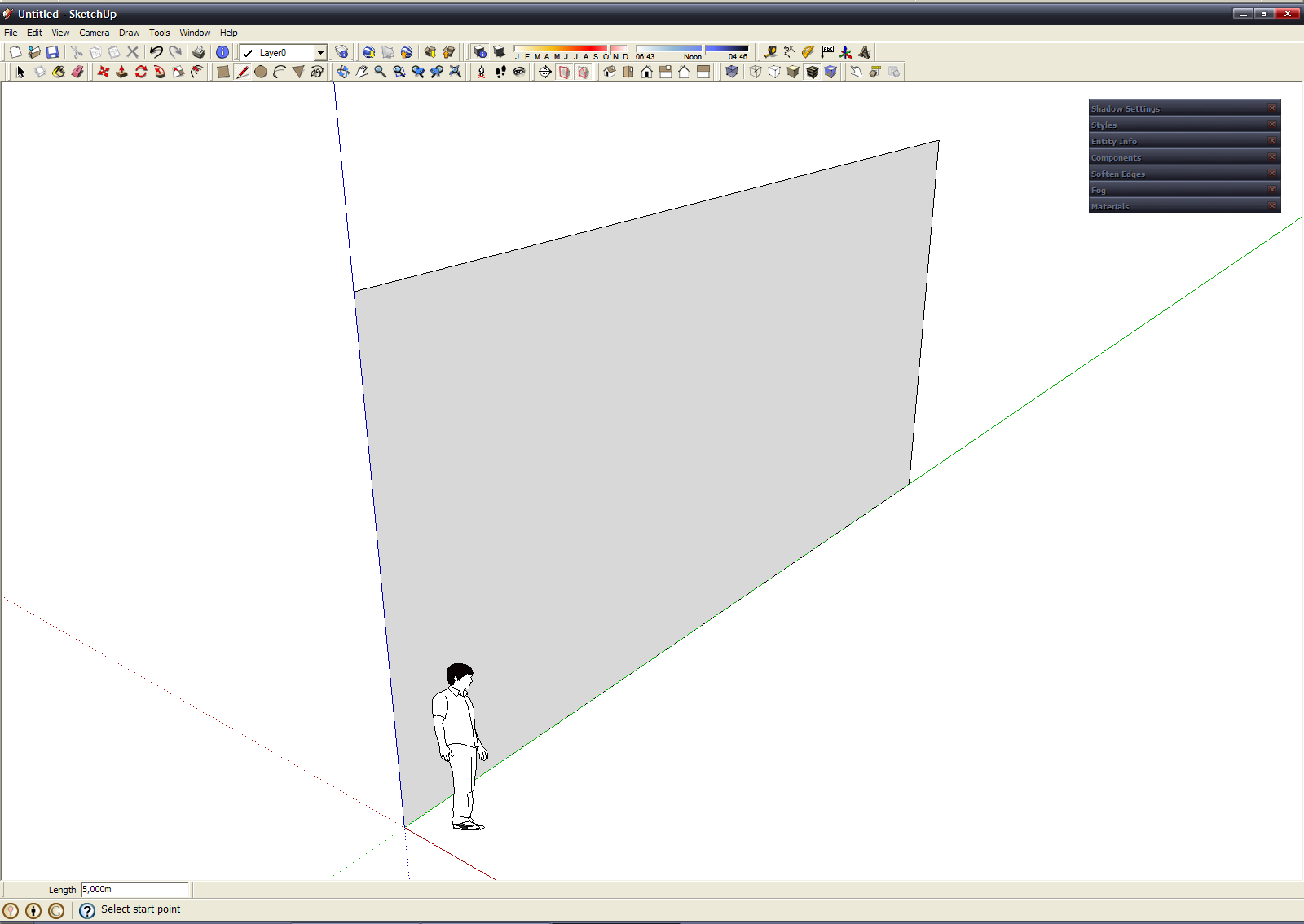
At first create diametral plane, width and height are equal with our aircraft, or more on a couple of meters. Also on this plane we can apply blueprint from internet, or your 2D drawing (as texture), but I don't use this feature, becouse often modeled direct from my fantasy.
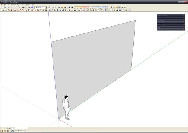
For creatin plane I sed "Pen" tools from "Drawing" toolbars.  ut in into centre of coordinate, send parallel green axis, type "10" at keyboard and pres Enter key. Then send line up, type "5", later again parallel to the green axis in the opposite direction, and when I return into starting point - I have a plane. When our line are parallel some axis, then line have a color of this axis (as hamaleon =). Сomfortably. Until we dont ended line, we can type their lenght from keyboard (lenght is showed in input box at status line) ut in into centre of coordinate, send parallel green axis, type "10" at keyboard and pres Enter key. Then send line up, type "5", later again parallel to the green axis in the opposite direction, and when I return into starting point - I have a plane. When our line are parallel some axis, then line have a color of this axis (as hamaleon =). Сomfortably. Until we dont ended line, we can type their lenght from keyboard (lenght is showed in input box at status line) 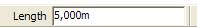
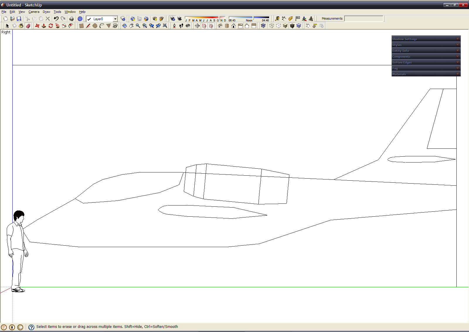
Then we draw silhouette of an aircraft at our surface. Use "Pen" tool too, also we can use "Arc" tool (button placed near "Pen" button at same toolbars).

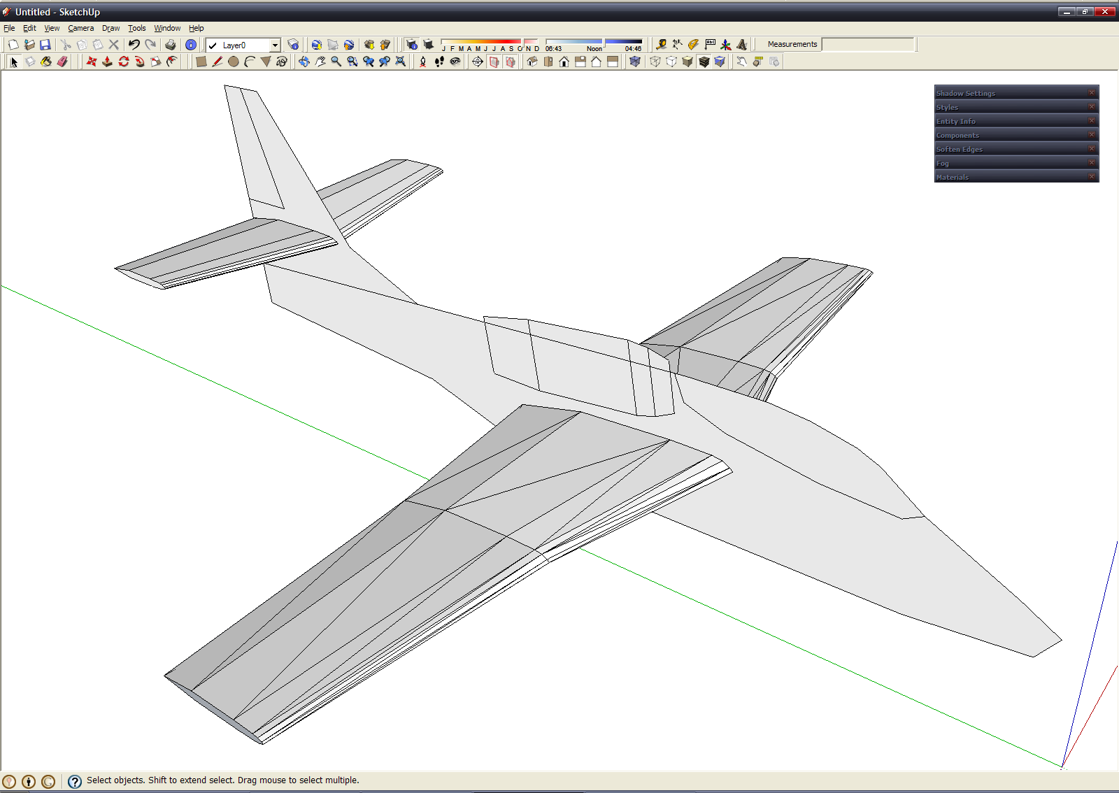
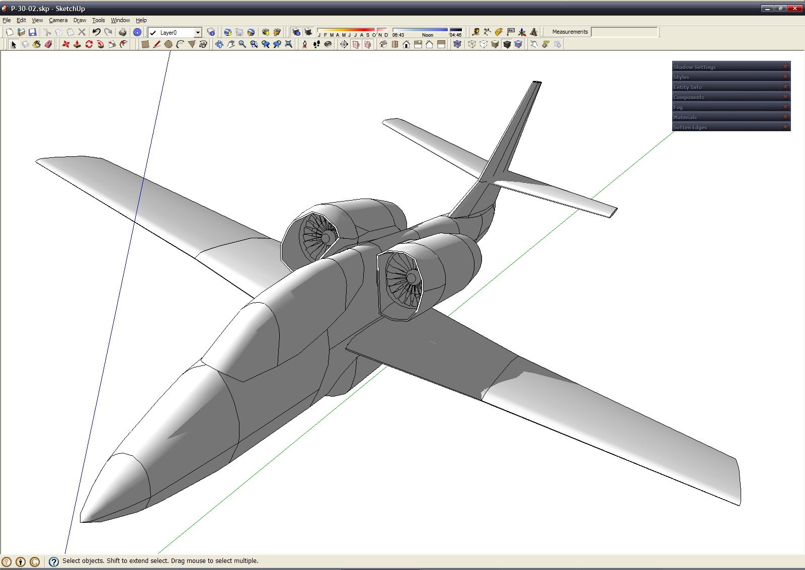
I have light trainer jetplane. Besides silhouette I drew cockpit, jet engines and airfoil of wing and horisontal stabilizer (tail wing) Then create wing. For this I used "Push/Pull" tool at "Edit" toolbar.  Pull airfoil away and pull back on the half-length with pressed Ctrl key. You should get this: Pull airfoil away and pull back on the half-length with pressed Ctrl key. You should get this: 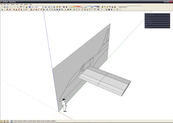
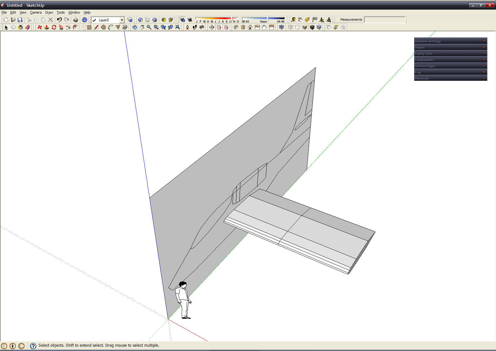
Then change size of part of the wing farthest from the fuselage - use "Scale" tool at "Edit" toolbar. 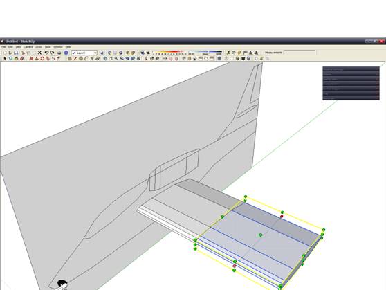
After some manipulation with "Scale" and "Move/Copy" tools we have half of wing. Analogical created horisontal stabilizer:

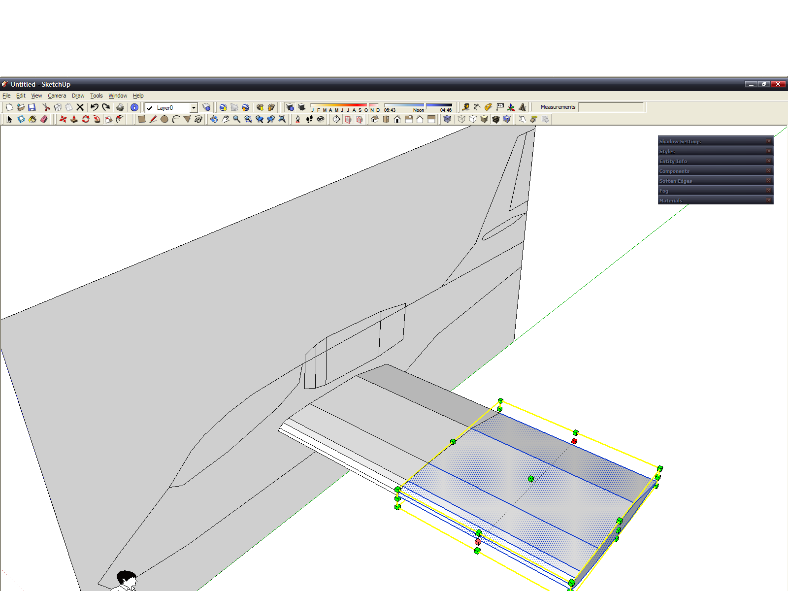
We can copy ("Move/Copy" tool with pressed Ctrl or Ctrl+V) and mirror (set Red axis herewith) our model for get left and right part of wing and stabilizer (I usually modeled only one side of model, and after complete, copy and mirror it for get complete model of aircraft - becouse almost all aircraft are symmetrical) 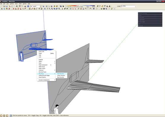
Combine the vertex and remove unnecessary part of diametral plane, we get this:
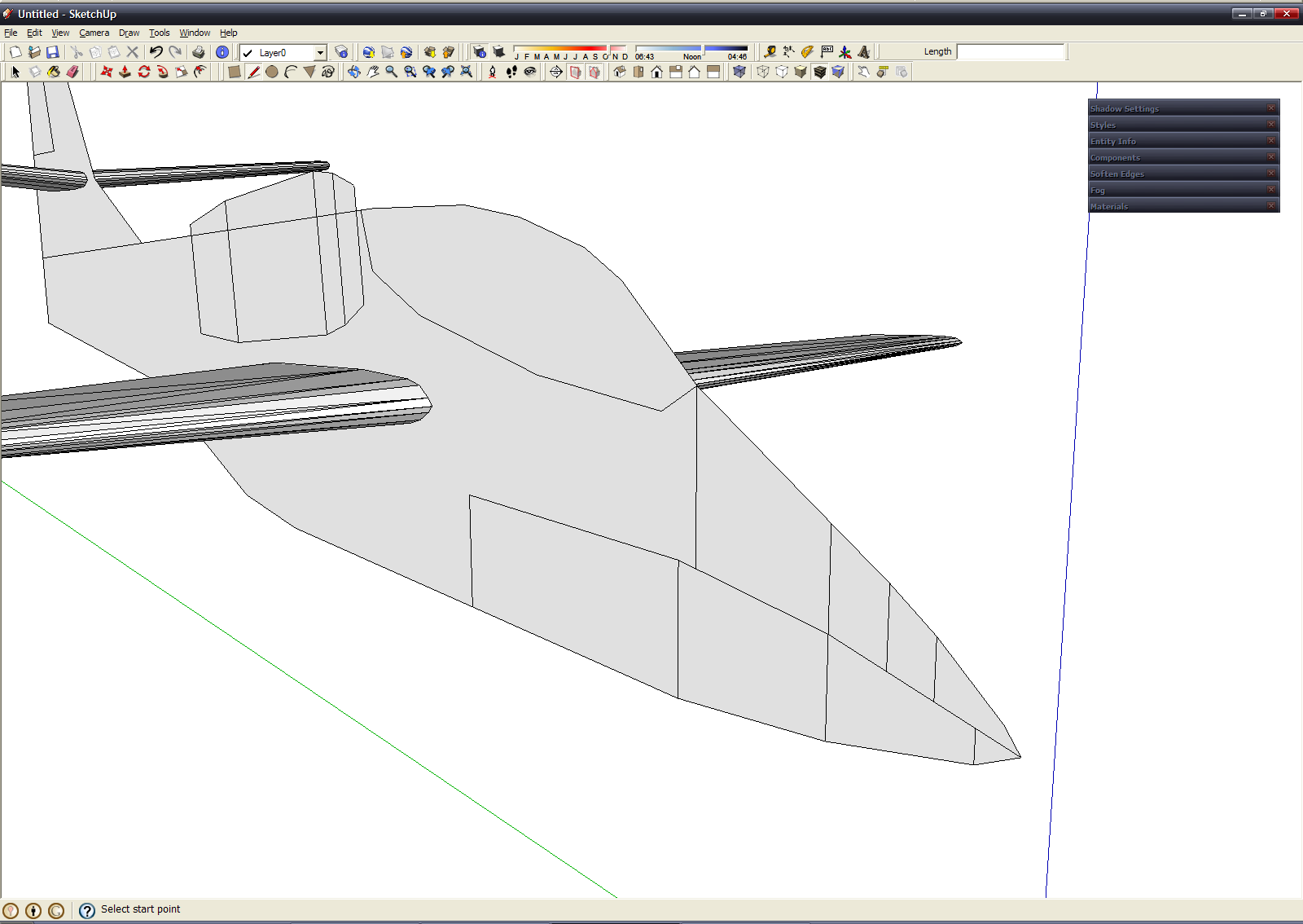
Start modeling of fuselage. With my method this is a most laborious stage. Forget about the engine =). From all vertex, that create the silhouette of fuselage, draw vertical lines, also draw line in presumably maximum width of fuselage. We must get this:
Then create couple auxiliary perpendicular surface and draw cross-section at them, to get this: 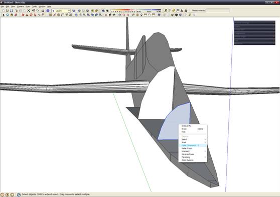
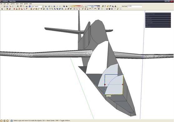
Now a very interesting technique. Copy the surface, make it a group (on the screenshot), copy to a new point of intersection, and resize it under the contours of the (if not make a group it will distort the contours), then "Explode" command from context-menu (right click) (it becomes part of the object):
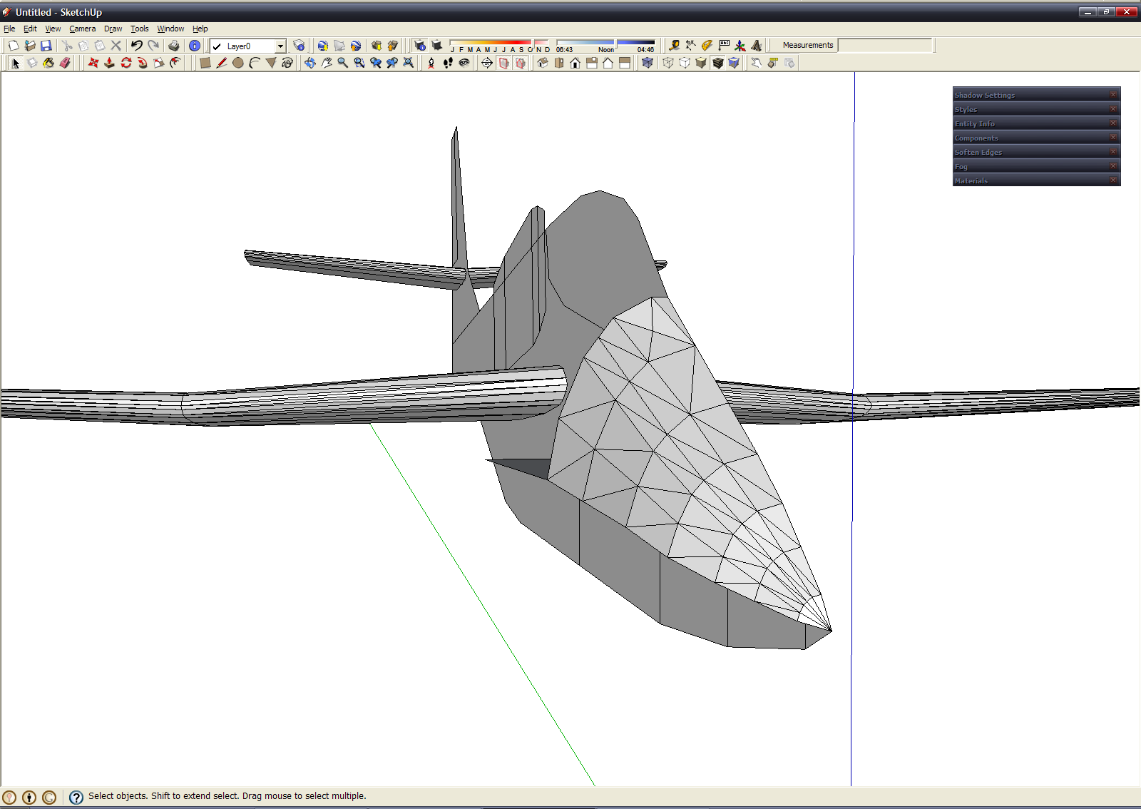
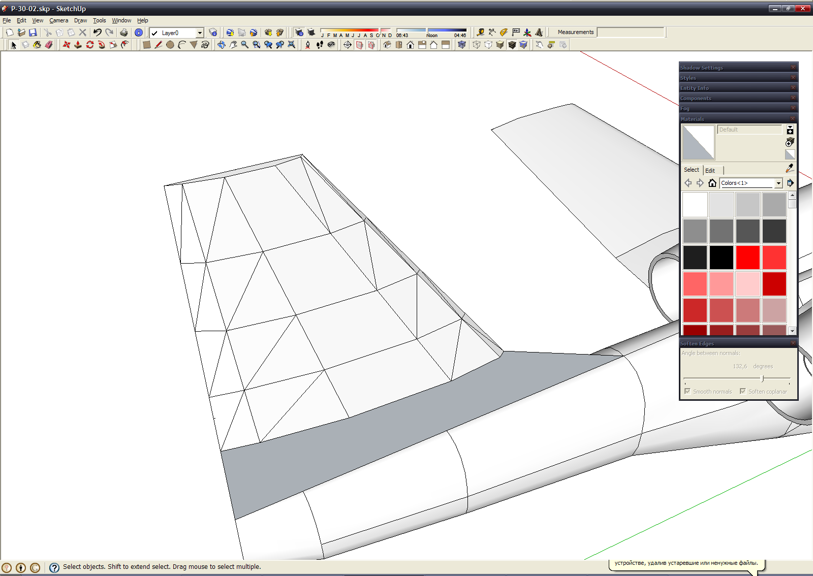
Next we can create a mesh, just connecting vertex by dint of edges (use "Pen" tool): 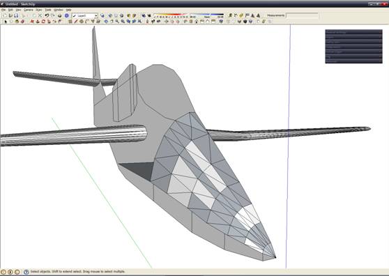
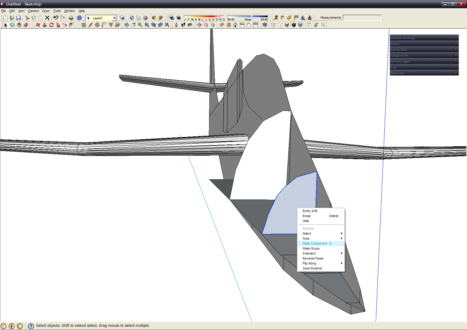
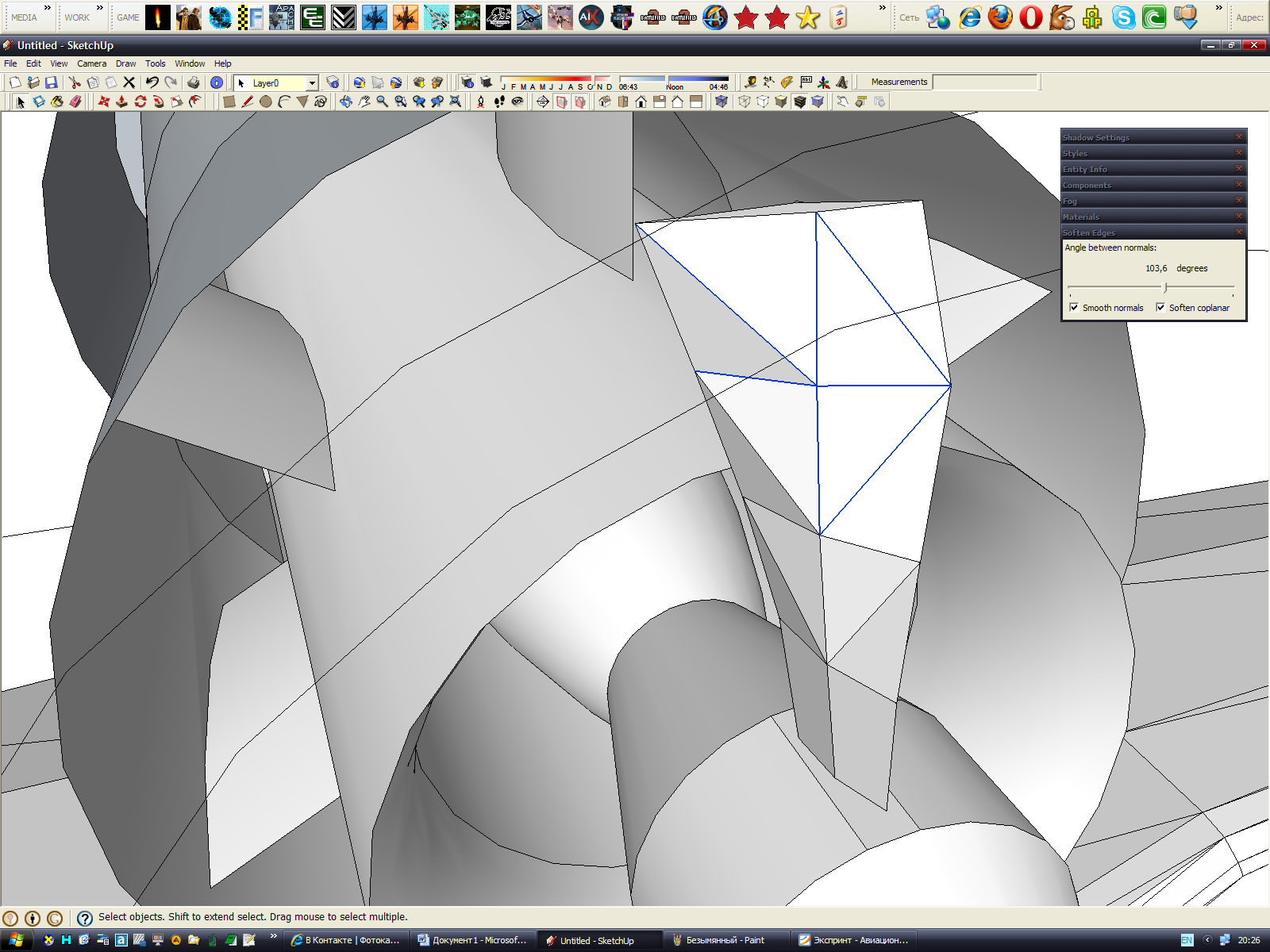
Note - the polygons, painted into gray color, have normals directed away from us (inside of mesh) - this is a problem - becouse many 3D software and video games don't render these polygons, and we get model with many triangular holes =). For correct normals direction we must select polygon (or many polygons with pressed Ctrl) and excecute command "Reverse faces" from context-menu.
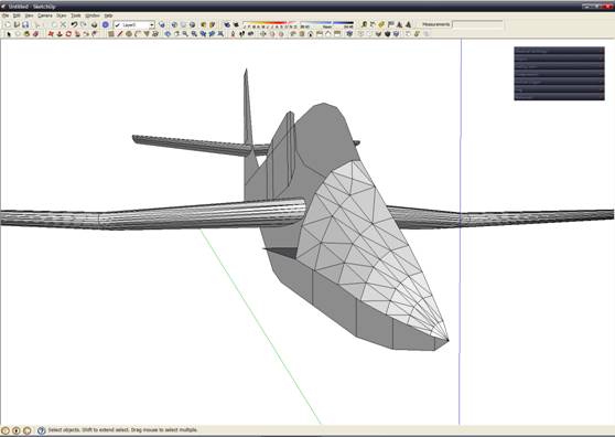
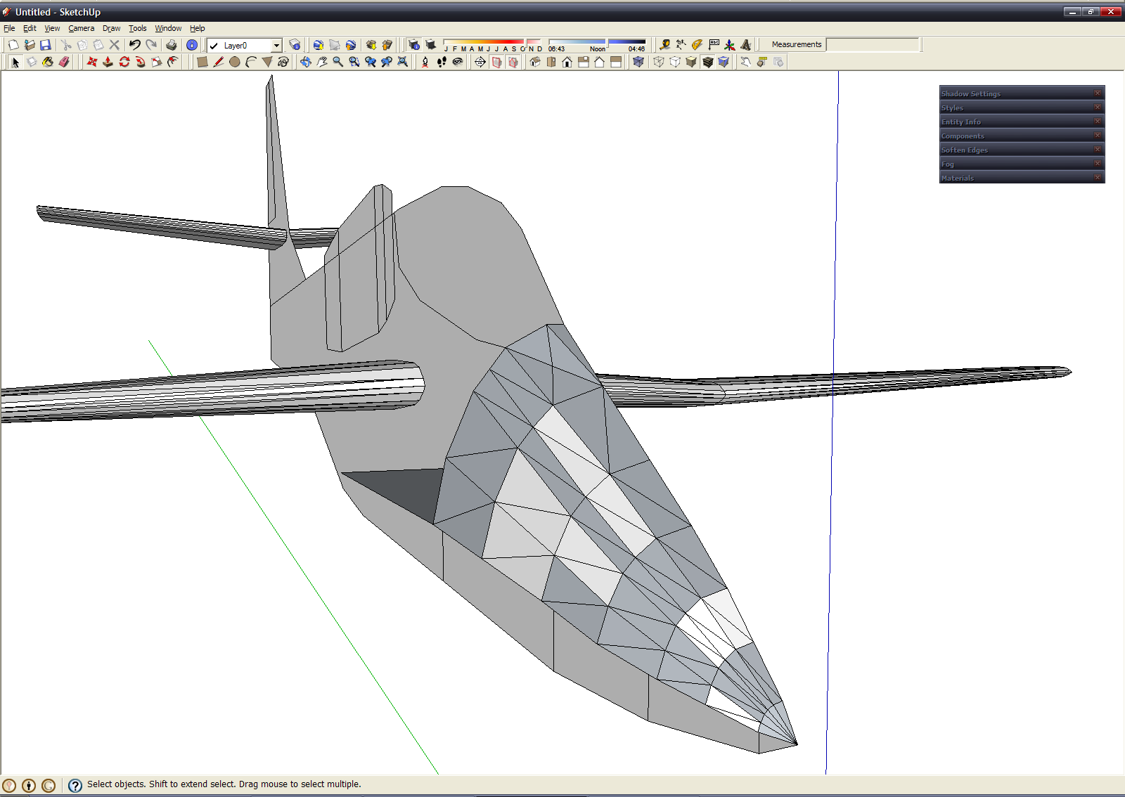
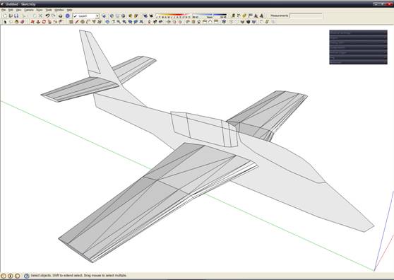
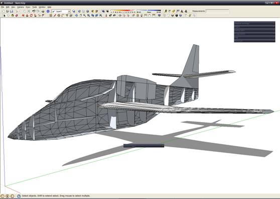
I think, that you get the general idea. Now I create all fuselage with this method and create some screenshots at different stage. 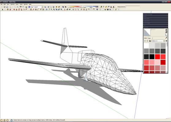
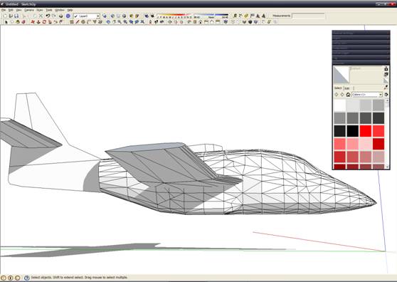
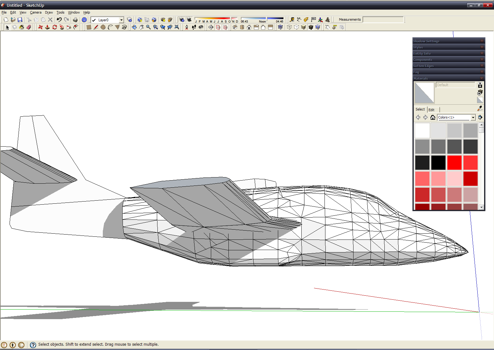
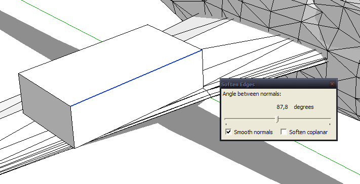
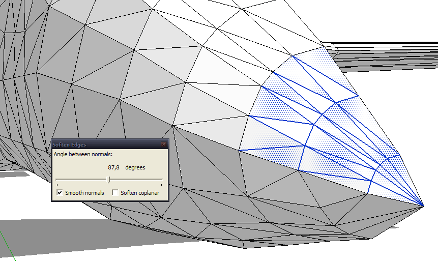
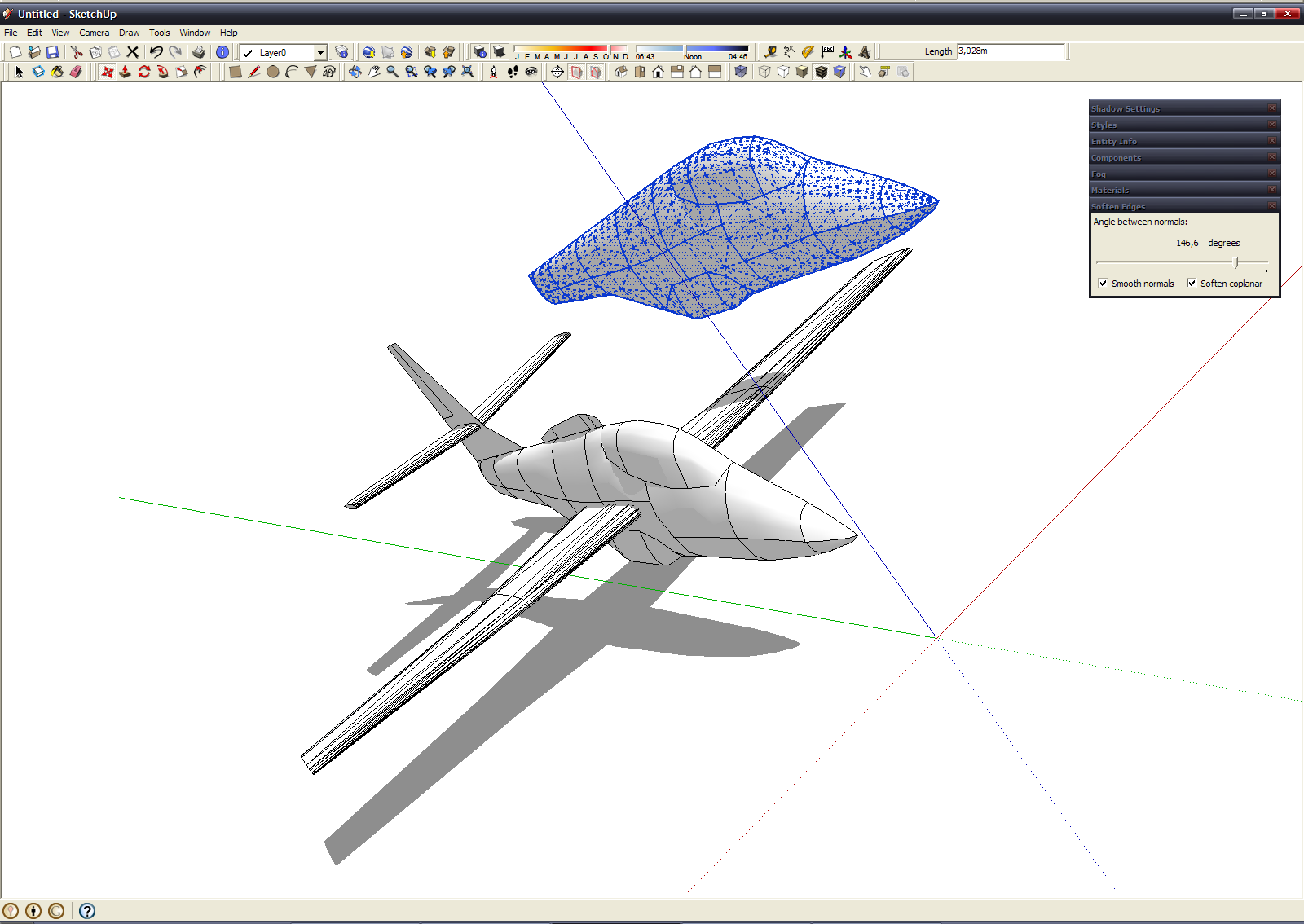
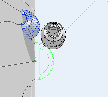
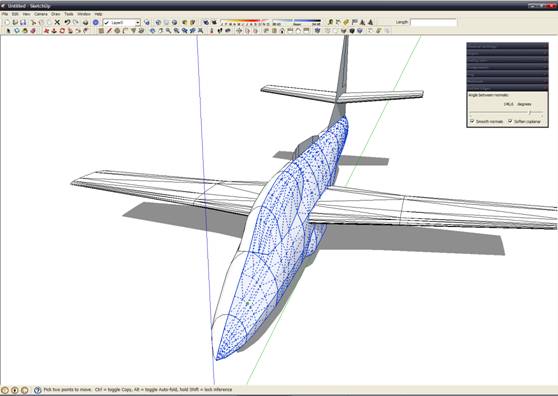
In general now we can copy and mirrored opposite part of fuselage, but I want to do one operation, before this - smooth edges between some polygons, for smoothed surface. For this we select line and into "Soften edges" window move the slider to set angle between polygons, when edge will be smoothed (for example - to get smooth edge in cube we must set angle over 90 degrees) 
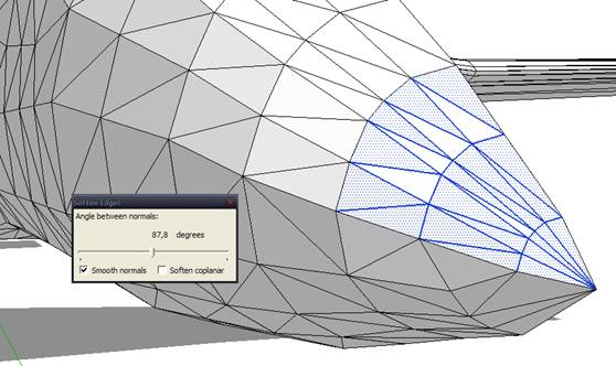
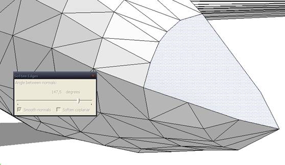
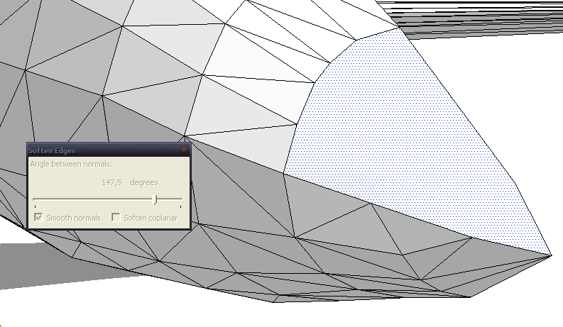
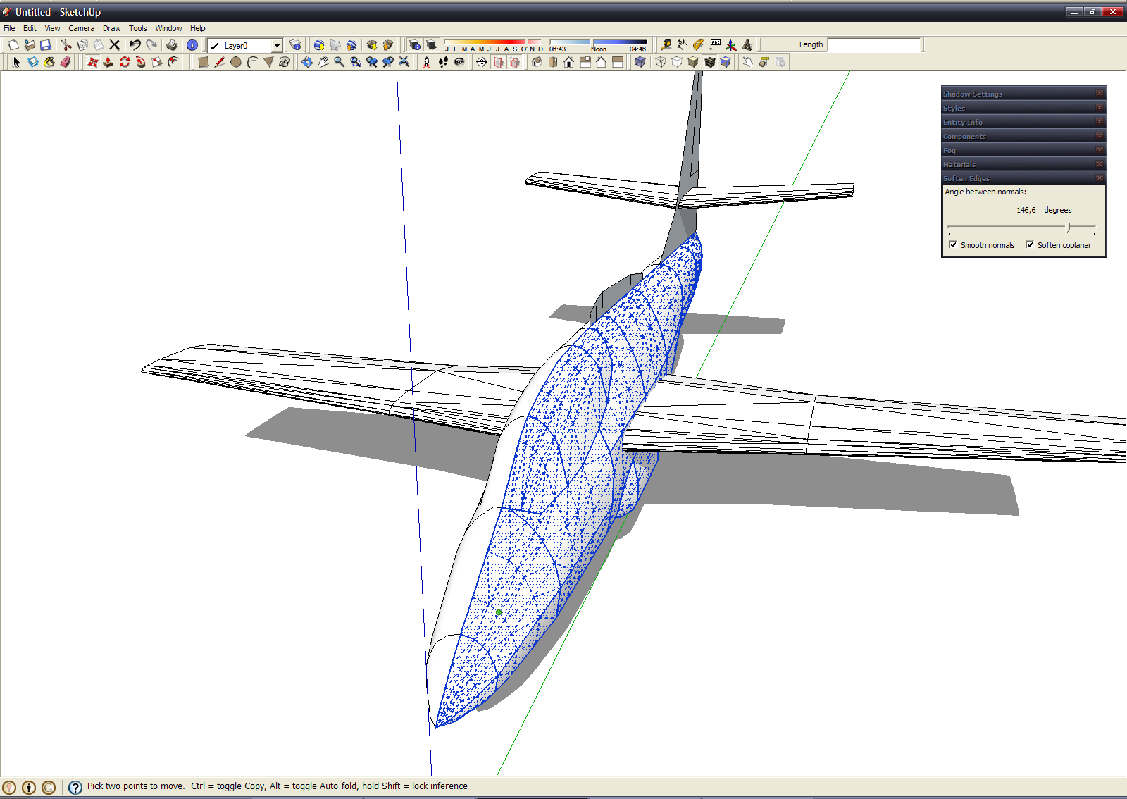
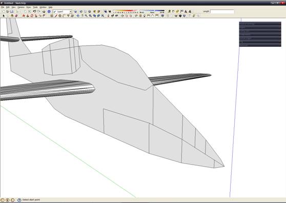
Sometimes we need only touch a slider. If polygons are parallel (angle between it is 180), then enable the "Soften coplanar" checkbox. Smoothed all fuselage surface. Dont forget remove auxiliary surfaces inside fuselage - now it not required:
After this operation we get:
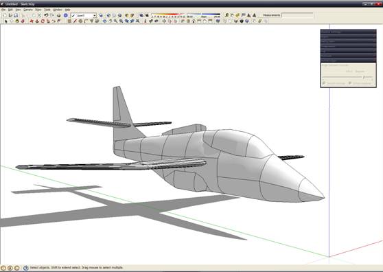
Now we copy opposite part: 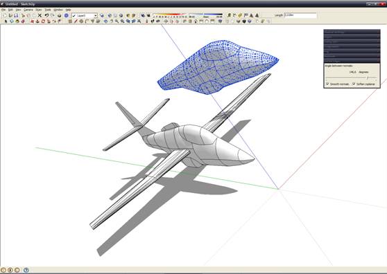
"Flip along->Red direction", combine the vertex and have complete fuselage:
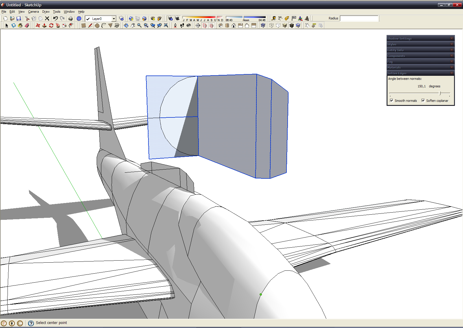
Now we must remember about engine. Copy it contour from diametral plane, move into convenient location and start modeling. In spite of the form of air intake, engine has a round cross-section. You could turn their contours parallel to Green axis, for comfortability work. We will model it very detailed, up to turbine blades (for love of the game). 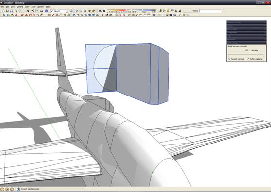
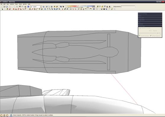
On this screenshot we can see simple cross-section of engine - turbofan=)
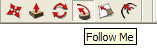
For body of revolution we use "Follow me" tool: 
Draw circle at perpendicular surface, next (with "Follow me" tools) select contour and turn it around circle (or half circle and mirror it, but sometimes we have some troubles with half circle - full circle better as me) 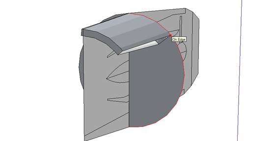
Also "Follow me" tool can used not only body of revolution, but for other shape...
Create by this method one combustion chamber: 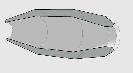
Then copy it with "Rotate" tool with pressed Ctrl key: 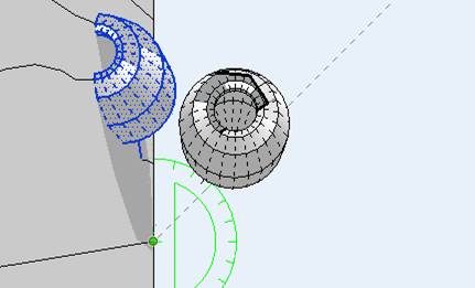
We must fill all circle with this parts. Engine contour with all combustion chambers look this: 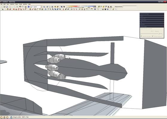
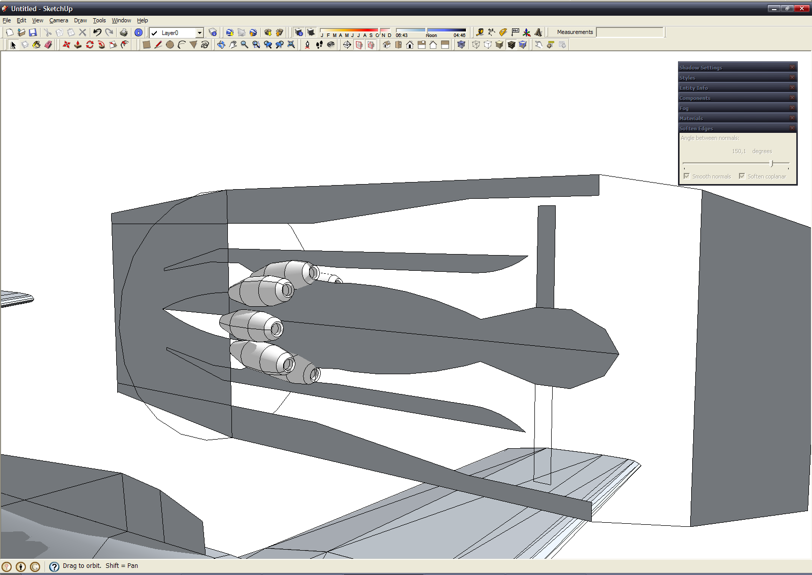
Complete all "body of revolution" and placed all combustion chambers we get this: 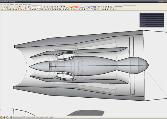
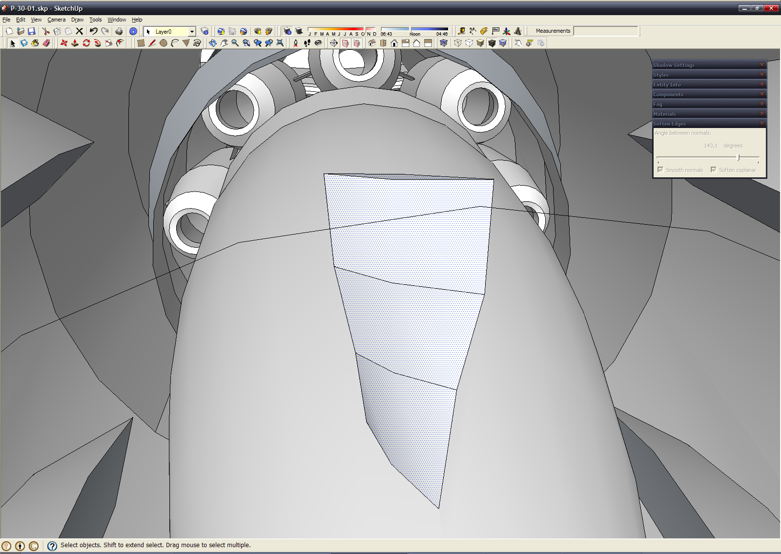
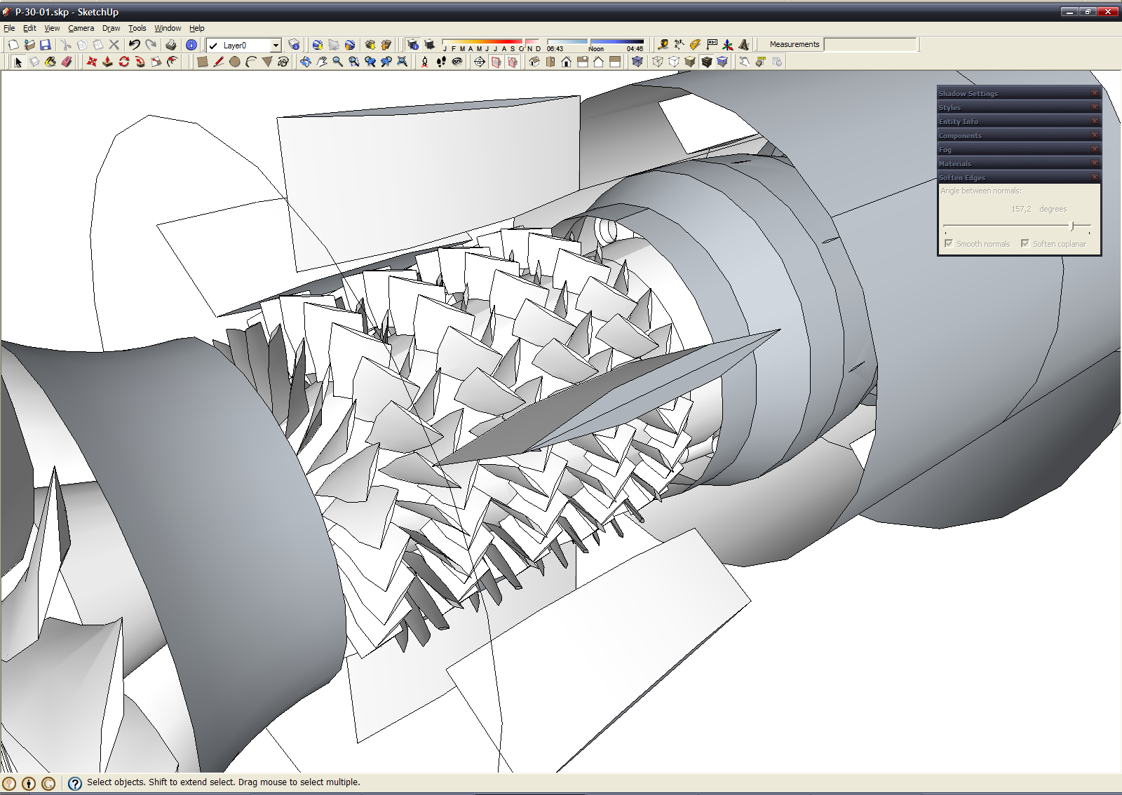
Then we need combine all of these "complex shaped" tubes with connecting riser and create blades of fan, compressor and turbines. A blade of fan (a rhomb pull up, split into 4 parts, rotate every part relative previous at couple degrees, increase size of every part relative previous) look this: 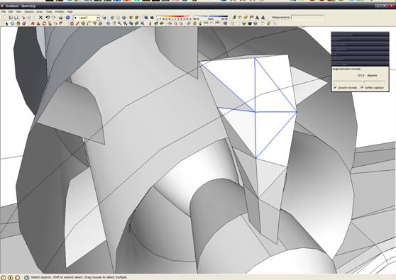
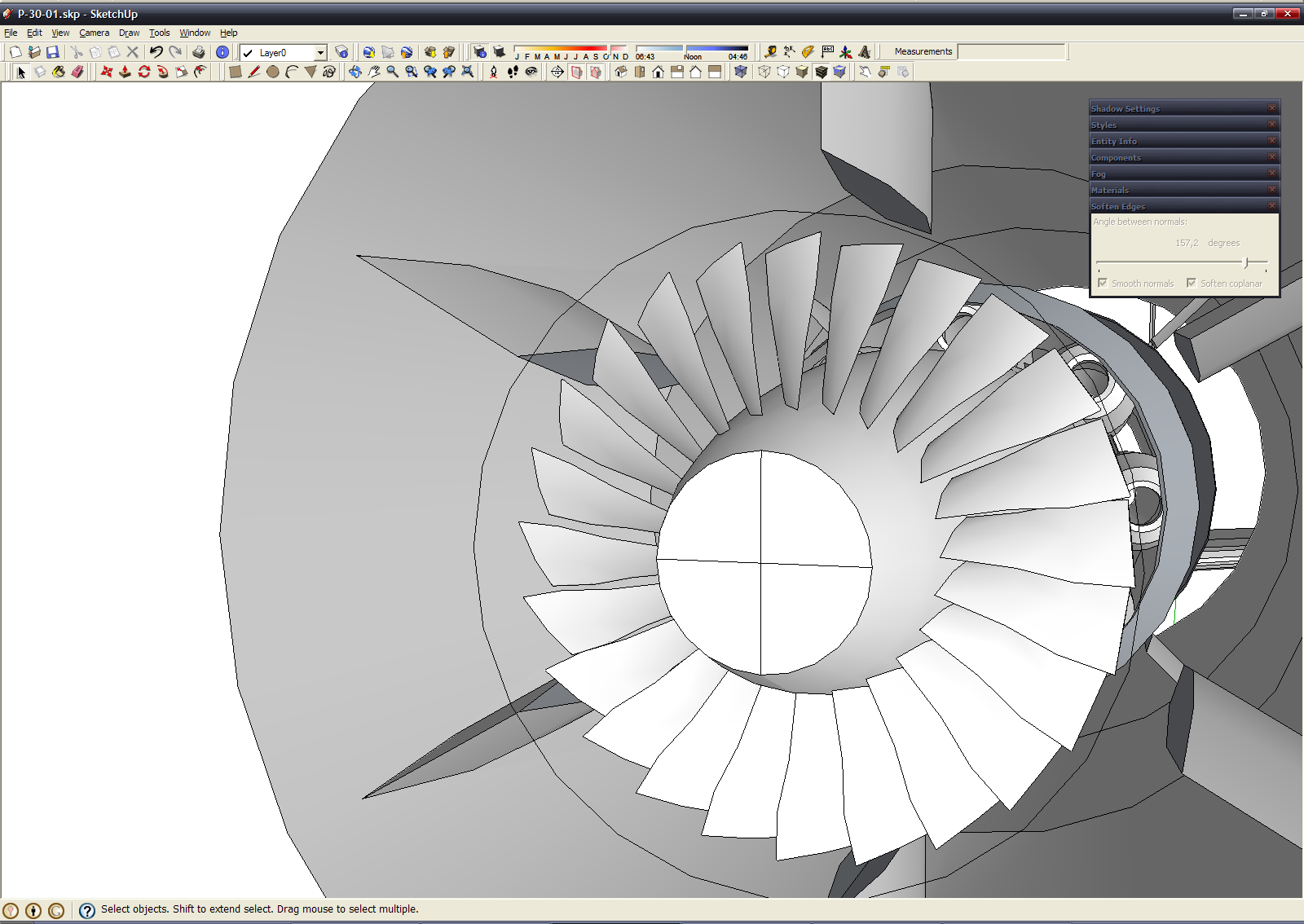
Completed fan looks this (used same method when we copy combustion chambers):
A blade of first compressor's stage looks this: 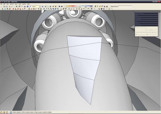
Complete first stage: 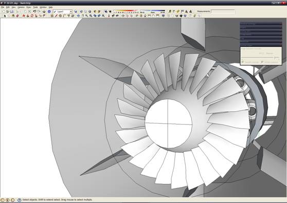
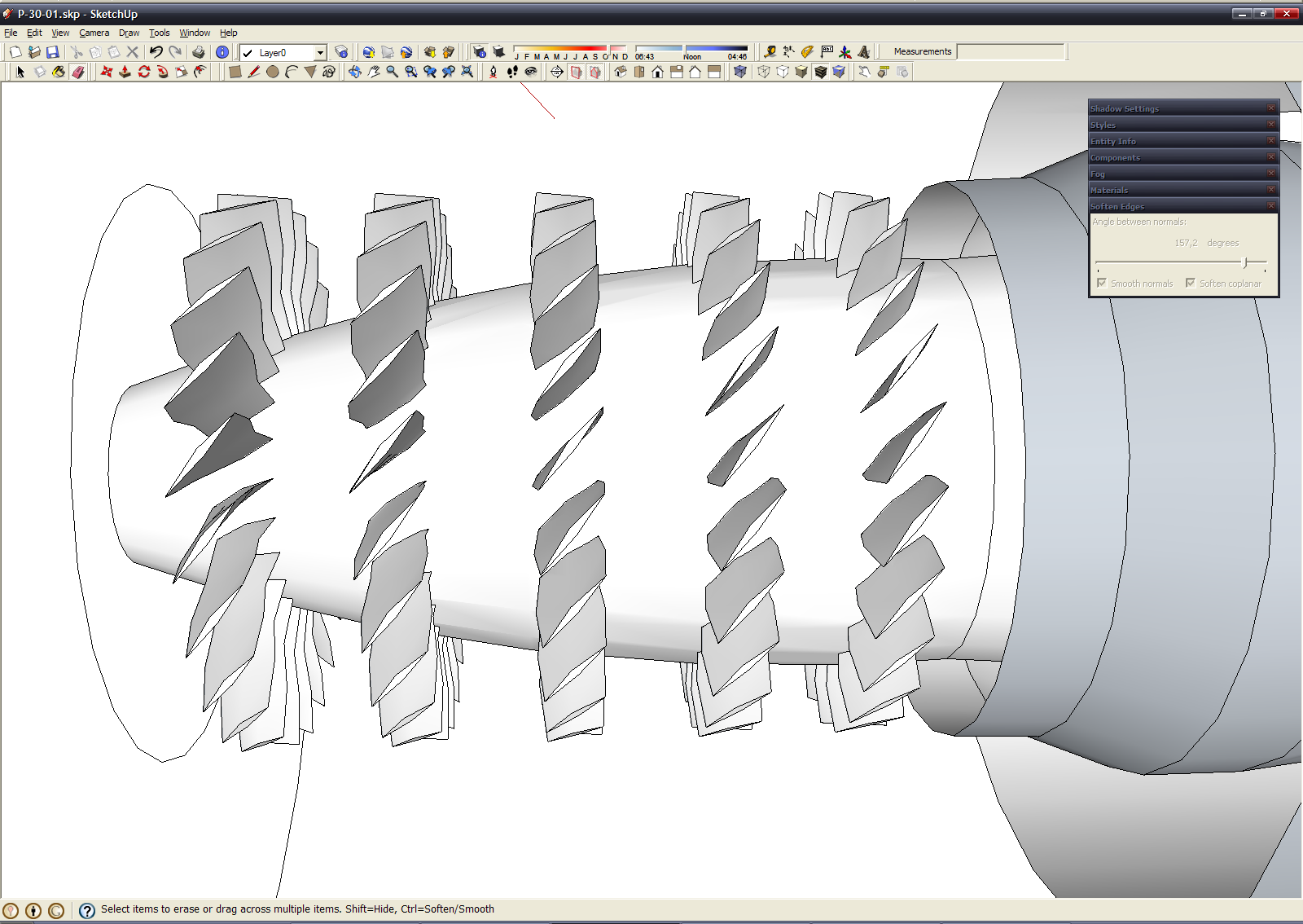
Using copy-paste method we get full compressor device of engine: 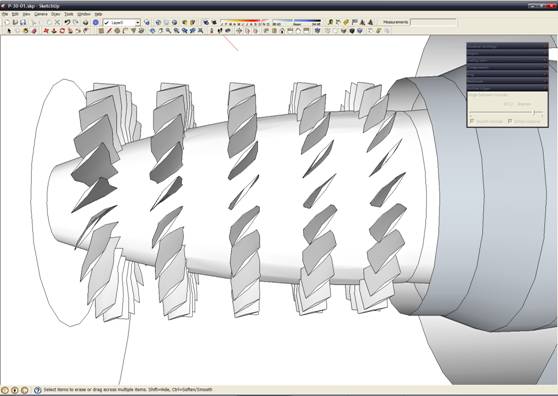
Don't forget remove parts of blades into central "body of revolution" into compressor device. Now we must create one detail - the stationary blades of the stators. Just copy compressor blades, mirror it and paste into corpus between compressor's disk Now compressor complete: 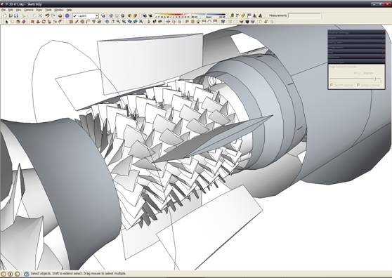
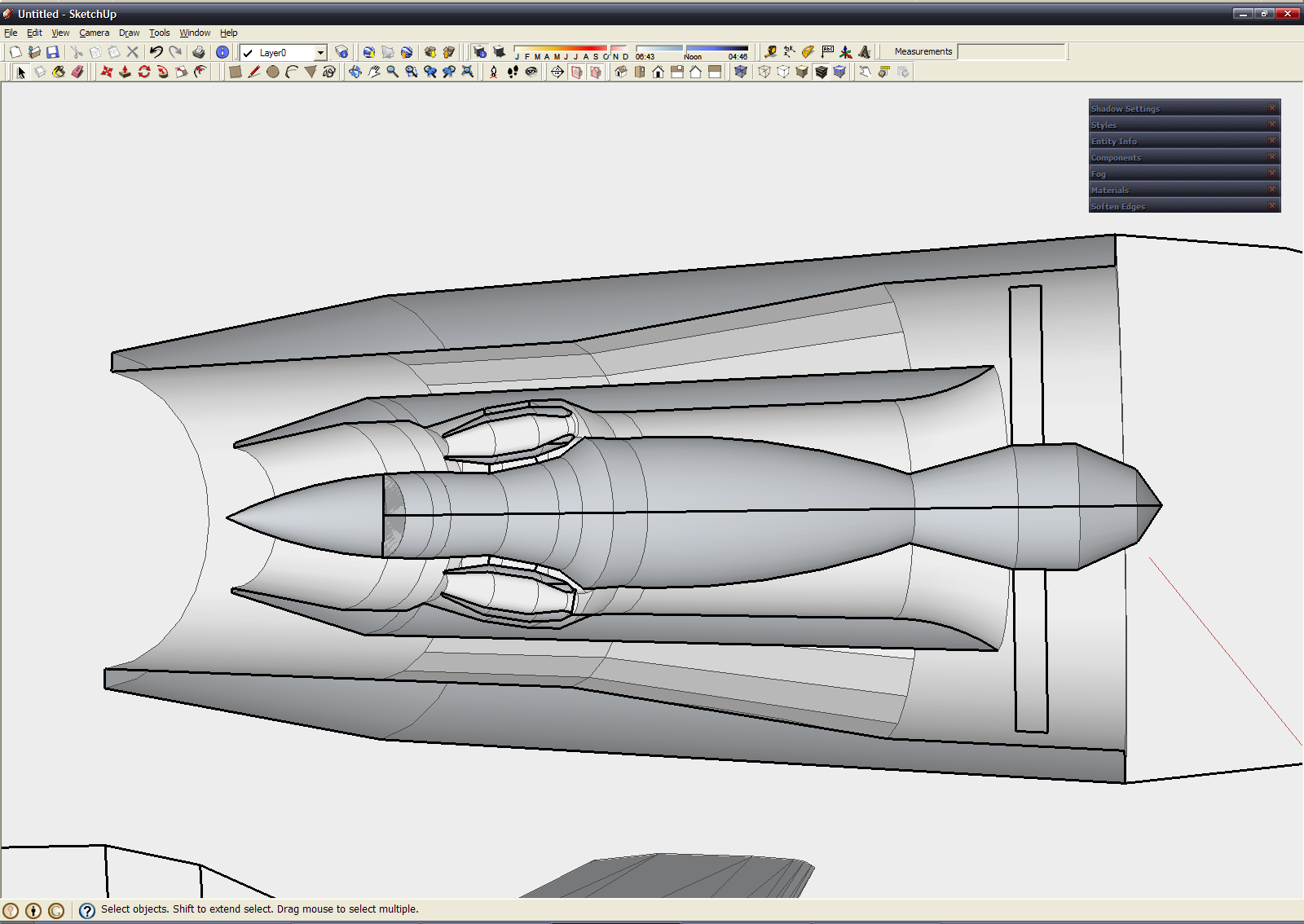
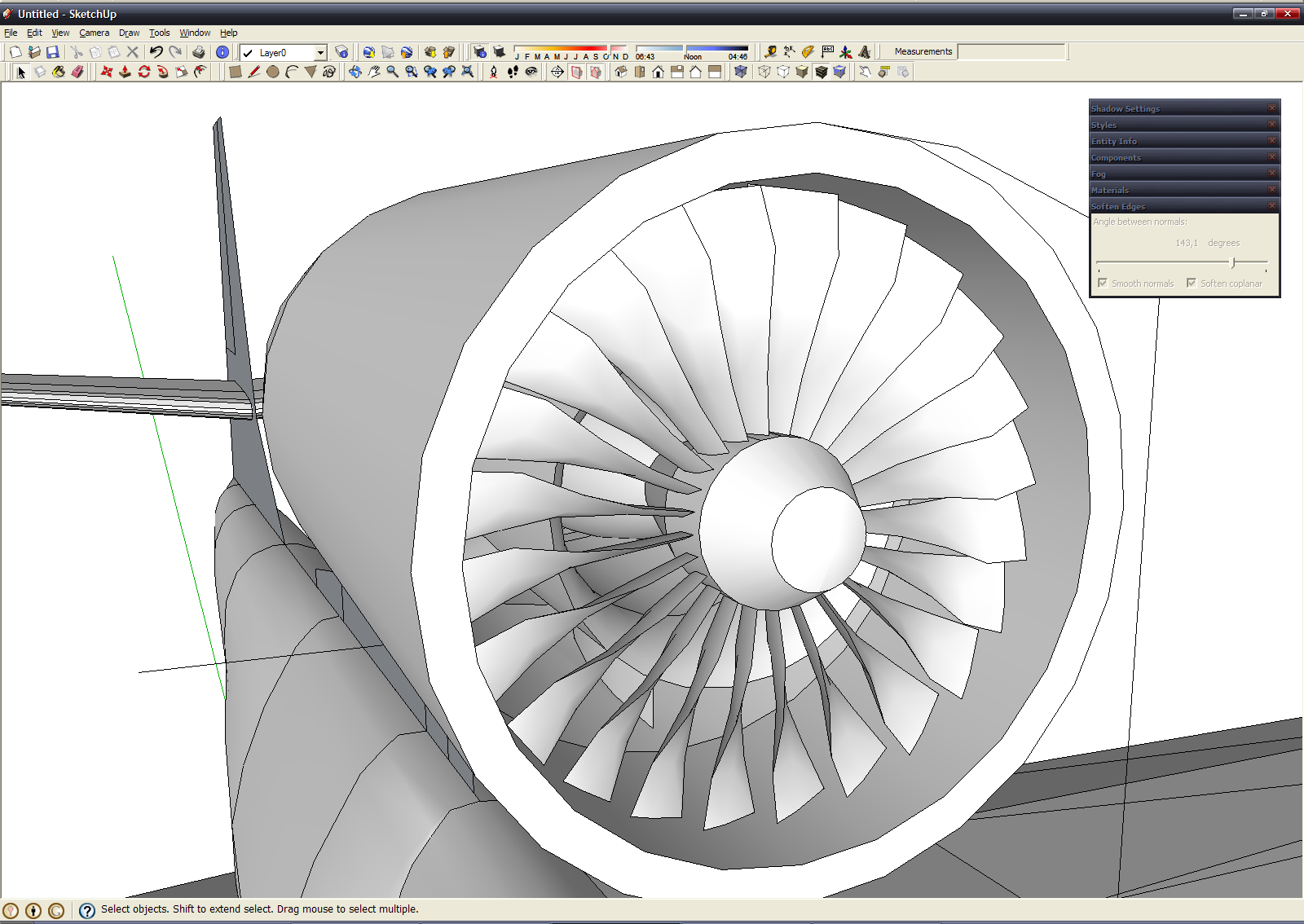
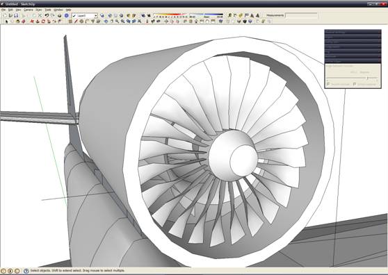
Finishing touch - turbine's blades. After completing - engine ready to installation on board =) 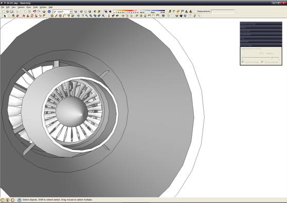
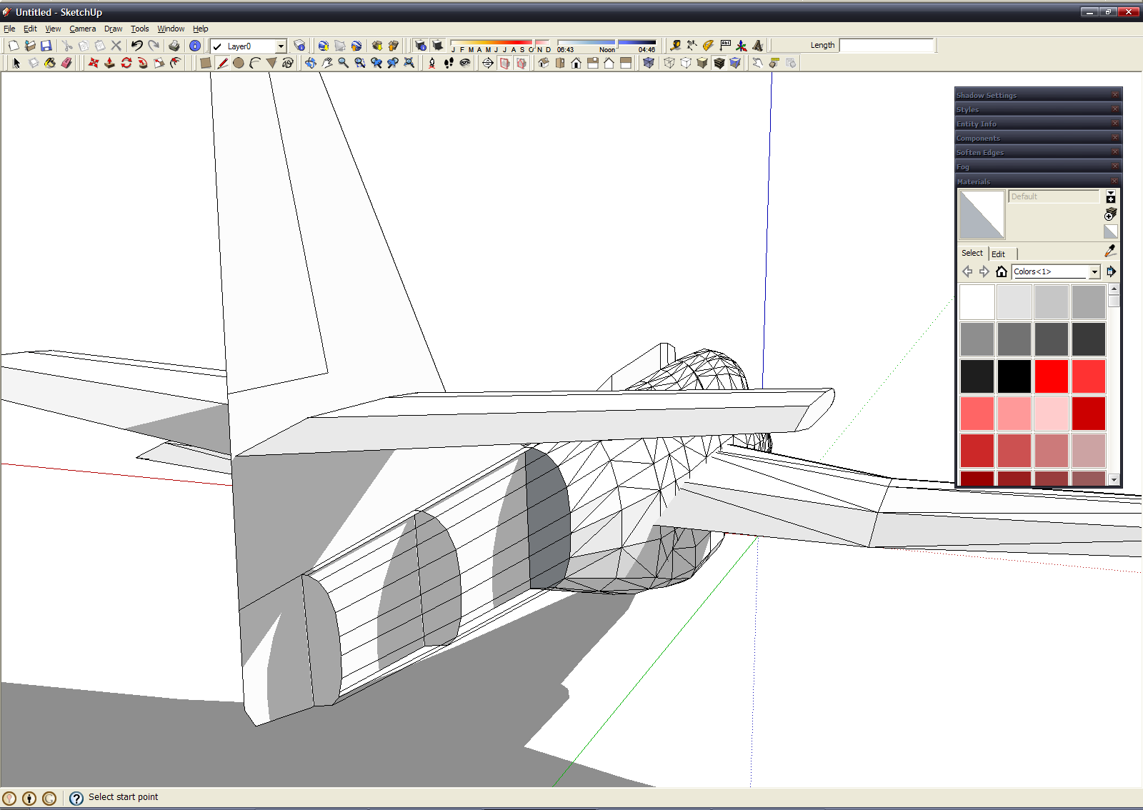
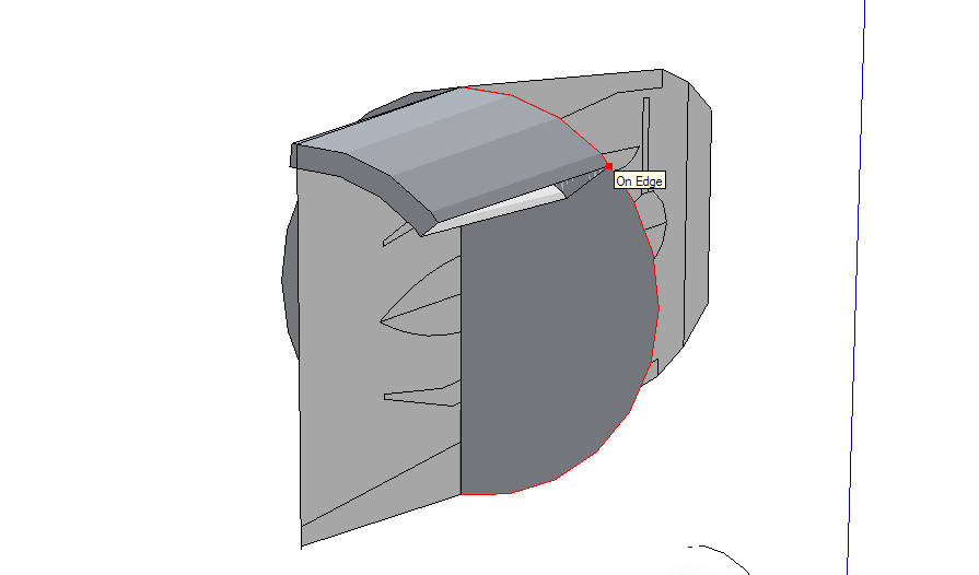
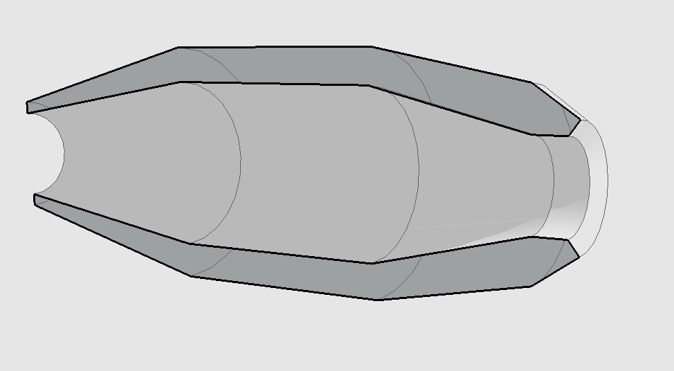
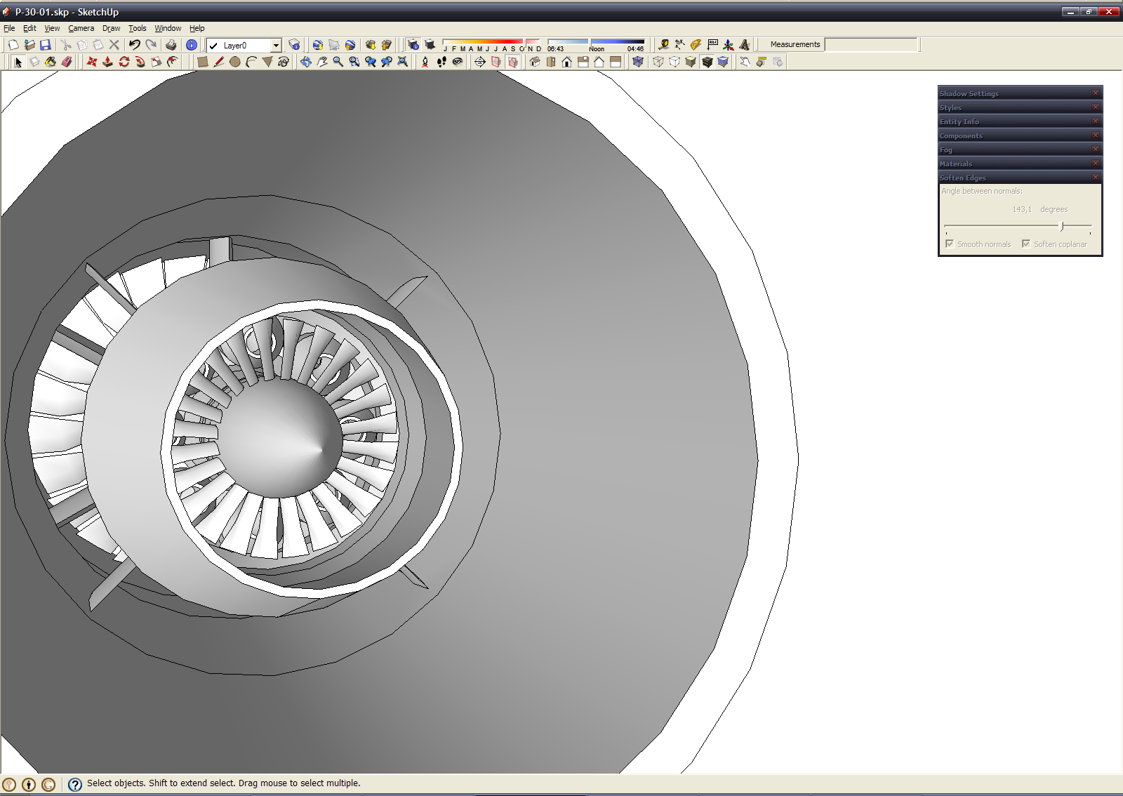
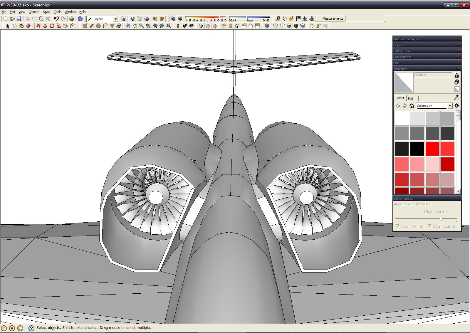
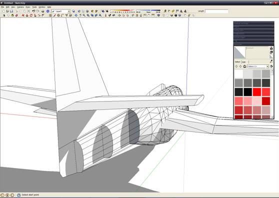
Now engine complete - select it and create individual group to prevent accidental damage. When engine installed, we must create air intake and engine nacelles: 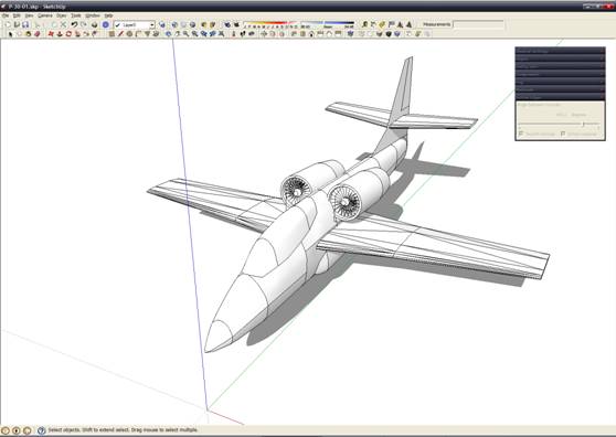
General view of engine nacelle: 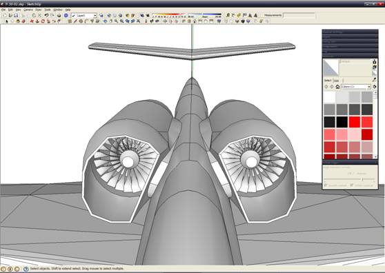
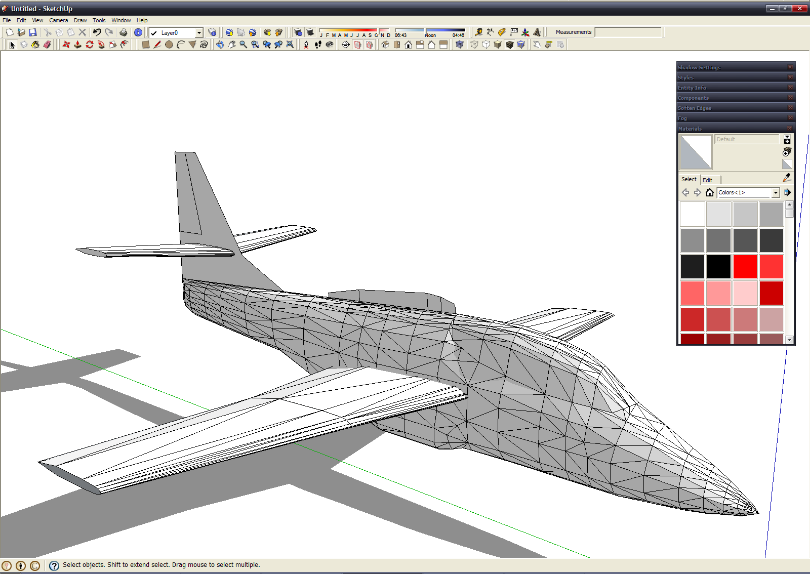
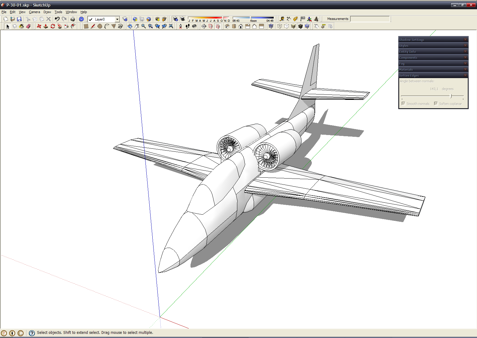
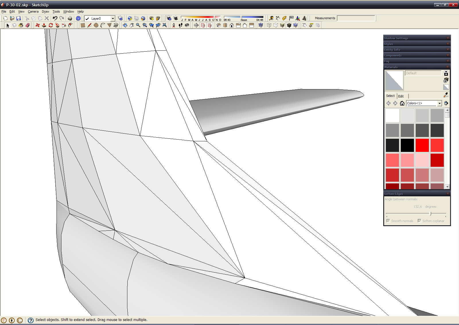
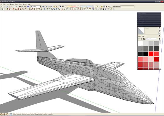
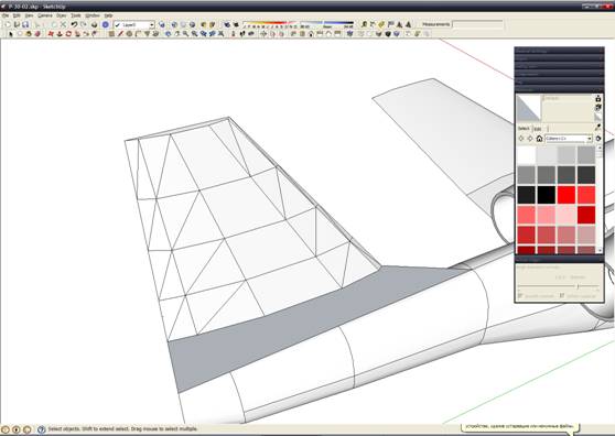
After this - tail fin. Use same method when we create fuselage.

At this I stopped - first part complete. To be continue (in russian language all was written years ago, but still requires translation). 
|